Where Am I – Making sense of vertex positions in Unity
This is a beginners tutorial for people who are starting out writing vertex and fragment shaders in Unity. One of the hardest things for me to figure out at the beginning was which input values I would be working with in my shaders.
Even after reading and watching quite a few number of tutorials nobody it still took a fair amount of experimenting for me to fully understand it. The aim for this post is to put my learnings into words and maybe help someone else who is going through the same process as me when I started out writing my own shaders in Unity.
Passing data to the shader functions
Unity uses structs with semantics such as POSITION, NORMAL or TEXCOORD0 to pass data to the shader functions. The position of the current vertex is supplied to the vertex shader, transformed by the vertex shader and then passed on to the fragment shader. In addition to the vertex position Unity can also pass addii<onal data along such as information about the UVs and any constants you define for your material.
We’ll use Unity’s built in Unlit Shader to get started. It uses a data struct called appdata containing the current vertex coordinates as a float4 POSITION and a the first uv coordinate as a float2.
 struct appdata
 {
   float4 vertex : POSITION;
   float2 uv : TEXCOORD0;
 };
A couple of questions I had at this point is:
- What exactly is inside the vertex float4?
- Is this absolute or relative?
- If it’s relative, what is it relative to?
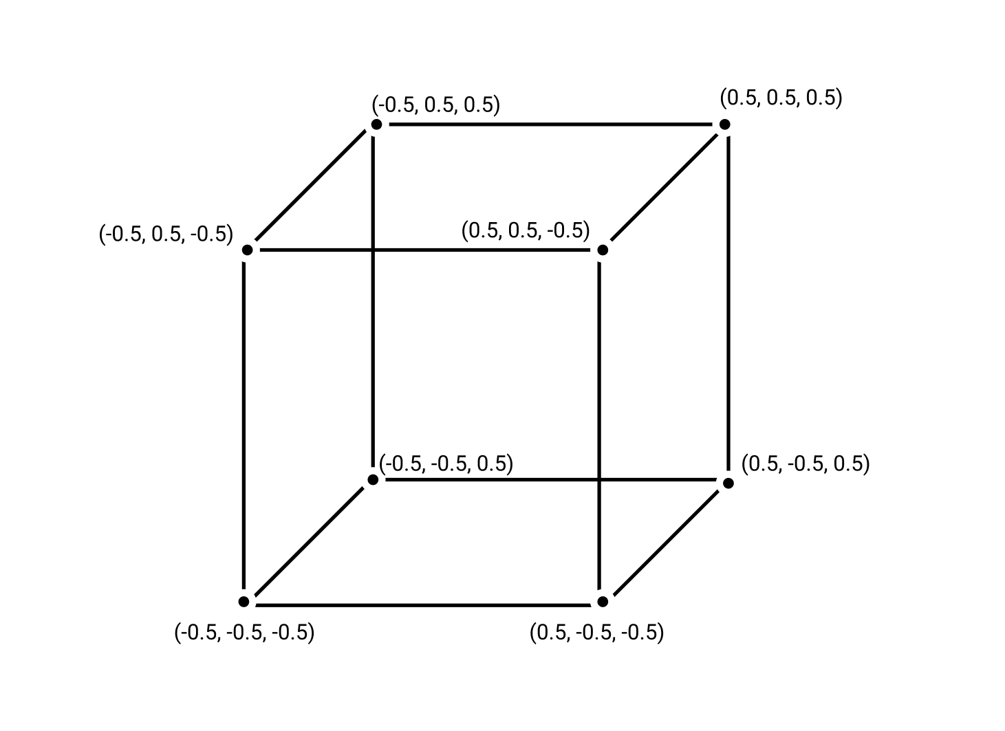
The first vertex position passed to the vertex shader is its position in Model Space.
Model Space
The vertex data passed through from Unity is a point inside 3 dimensional space with values that sit between -0.5 to 0.5. These values are always between -0.5 and 0.5 irregardless of how big or small the object is. The point tells us where we are in relation to the current model, but not in relation to other objects, lights or where we are in the world. This is called Model Space
In order to visualise this data we can pass the original vertex data from the vertex shader to the fragment shader and use it to colour the object.
...
struct v2f
{
    float2 uv : TEXCOORD0;
    float4 vertex : SV_POSITION;
    // Add another float4 to the object that carries the data from the verticies to the fragmet shaders.
    float4 original_vertex : TEXCOORD1;

};

v2f vert (appdata v)
{
    v2f o;
    o.vertex = UnityObjectToClipPos(v.vertex);
    // Pass the original data through here.
    o.original_vertex = v.vertex;
    return o;
}

fixed4 frag (v2f i) : SV_Target
{
    // Use the original vertex value to determine the fragment color.
    // X, Y, and Z map to R,G, and B in the fragment shader.
    fixed4 col = i.original_vertex;
    return col;
}
...
Full script on GitHub .
I’ve applied this shader to a sphere and a rectangle.
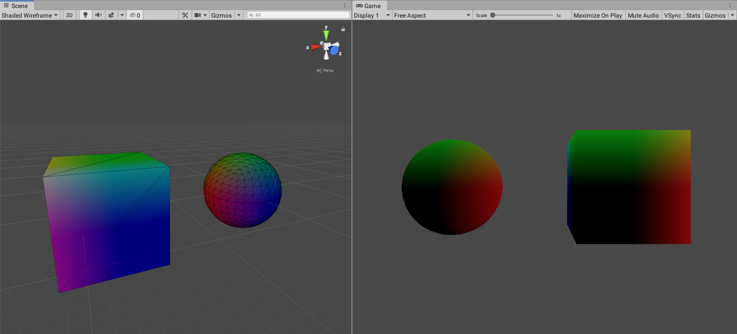
The resulting object is pretty interesting. The same shader is applied to sphere and a cube. The game view (on the right) shows the objects from the front. We can see that the bottom left corner of the models are completely black. Why is this? In model space all values sit between -0.5 and 0.5. All values in the bottom left corner would thus be less than 0 and render completely black. As we go higher up the object the it becomes more green and to the right it becomes more red. Because we mapped XYZ to RGB the higher up on the Y axis we go, the greener, and the greater the X value is the more red it gets.
In the scene view (on the left side) we look at the objects from the back. Here we can see that they are getting bluer. This is because the third coordinate Z maps to the blue value.
You have most likely noticed that the colours are still quite dark. That is because the model view only goes to up to 0.5 So the maximum value for any of the colours is only at half of its full intensity. To go the full spectrum we add 0.5 to the whole vector to change the lower and upper bounds to 0 and 1.
fixed4 col = i.original_vertex + 0.5f;
World Space
So far, so good. We now have access to the local position values inside of the vertex and fragment shader functions. But what if we want to know where in the world the object is and transform it accordingly?
Unity has a built in unity_ObjectToWorld matrix which we can use to transform our vertex data to the world position.
In order to visualise this I find it helpful to focus only on a single axis. In this case I’m going to focus on the X axis.
v2f vert (appdata v)
{
    v2f o;
    o.vertex = UnityObjectToClipPos(v.vertex);
  	// Multiply the unity_ObjectToWorld matrix with the model view
    // coordinate to get the location in world space.
    o.world_position = mul(unity_ObjectToWorld, v.vertex);
    return o;
}

fixed4 frag (v2f i) : SV_Target
{
	// Grab the x value and use it for every RGB value.
    float value = i.world_position.x;
    fixed4 col = fixed4(value, value, value, 1);
    return col;
}
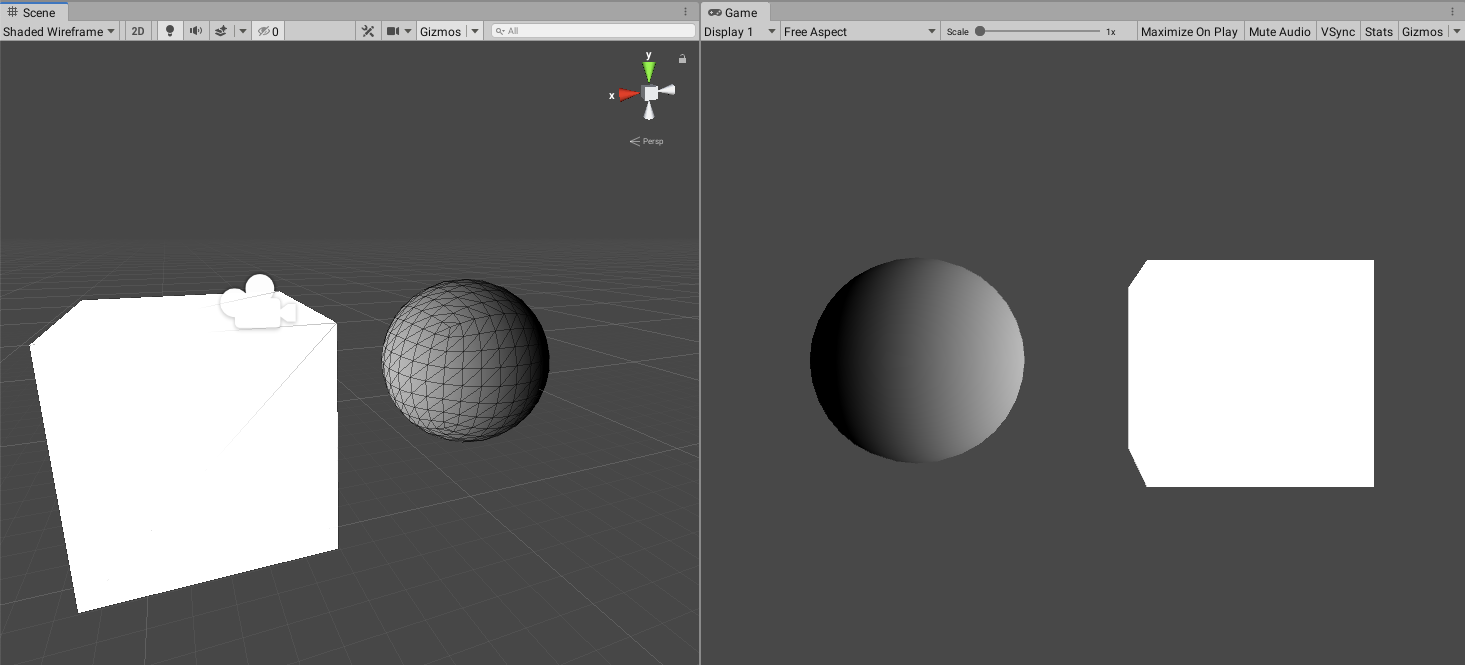
The surface is now completely monochrome. This is because we’re limiting ourselves to only one input parameter: the X value. The cube is completely white because in World Space it all of its vertices have X values greater than 1. The sphere sits beautifully between 0 and 1 on the X axis giving it a that gradient tone.
View Space
In the next transformation we take the World Space coordinate and turn it into view space by multiplying it with the view matrix which Unity supplies us with as well. The resulting coordinate tells us where our vertex is in relation to the viewer / camera.
v2f vert (appdata v)
{
    v2f o;
    o.vertex = UnityObjectToClipPos(v.vertex);
    float4 world_position = mul(unity_ObjectToWorld, v.vertex);
    o.worldView_position = mul(UNITY_MATRIX_V, world_position);
    return o;
}

fixed4 frag (v2f i) : SV_Target
{
    float value = i.worldView_position.x;
    fixed4 col = fixed4(value, value, value, 1);
    return col;
}

Something weird has happened here! We’re still only looking at the value on the X axis but the colours in our scene view and game view seem to have been switched. For some reason the sphere is white in one screen and black on the other screen. The values we are now working with are in relation to the viewer. In the example above we have two different viewers which means the view matrix for the scene view is different to the one used in the game view resulting in different results depending on where the camera is.
The video below shows how the colour on the objects change when moving the scene camera, the objects or the game camera.
Projection Space
The final matrix multiplication we need to do uses the projection matrix. If you imagine the view matrix defining where the camera is in the world (and where it’s pointing), the projection matrix defines the type of camera and lens used.
In real world cinematography this correlates to the difference between a fisheye, a wide angle and a telephoto lens.
In Unity we can choose to use Perspective or Orthographic projection as well as modify the Field of View and other parameters that determine where on the screen the object finally ends up. In Unity the fisheye effect is not part of the built-in camera settings but needs to be added as an effect to the game camera.
View Space and Projection Space coordinates are not that different so no need to visualise it here.
Screen Space
The standard shader calculations do not take into account where on the screen the object/vertex/fragment is. If you want to use that information in your shaders you’ll need to do some additional calculations that I will save for a different post.
I hope this has helped someone who is trying to wrap their head around shaders and what values are passed through to the shader functions in Unity. Get in touch if you have any comments or questions!
References: